How to Use Semantic Workflow Graphs to Build Smarter Agents
As agents take on longer-running, more complex jobs, they need ways to track goals, source materials, output requirements, dependencies, validation rules, and fallback procedures. A Semantic Workflow Graph gives an agent that structure: clear guidance on the kind of work to produce, while leaving the agent flexibility in how to solve it.
In this guide, a Semantic Workflow Graph is a runtime model in which goals, artifacts, capabilities, dependencies, validation gates, and recovery rules are represented explicitly so an agent can reason about the work, not merely follow a predefined sequence of steps.
This article explains when to use a Semantic Workflow Graph and how to design one.
Semantic Workflow Graph: What It’s Good For
Semantic Workflow Graphs are useful when an agent needs to produce a specific output through complex, conditional work. The graph provides a guidance system enabling the agent to adapt without requiring prewritten procedures for every situation.
This can be a little hard to imagine, so let’s briefly consider an example: an AI workflow for creating a video ad.
Video ad production
If we implement an agent workflow for generating ads, a typical implementation might use a step-by-step process.
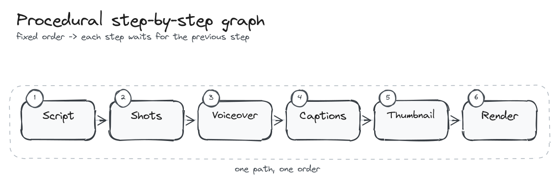
We can think of this as a procedural workflow graph. This basic Agent graph says, “run this step, then run that step, and maybe branch if a condition is true.” Each node is a step. An edge is the next step. The graph answers a narrow question: where should execution go after this?
However, there are limitations to this. First, it requires pre-designing every action that might be taken on the work. Second, to make changes somewhere in the chain, the agent has to rediscover the structure of the work. It has to inspect the ad package, figure out which assets it contains, invent new validation, etc.
In short the Procedural Graph is not flexible enough and doesn’t proactively provide the Agent with an overview of the entire work.
Using a Semantic Workflow Graph
If we give an Agent the same job as a Semantic Workflow Graph, it receives a richer context for how to build and revise an Ad. Such a graph would typically include the goal, artifacts, capabilities, dependencies, and validation rules that keep the work coherent as it changes. This organization of information gives the Agent a much more comprehensive view of the task and a better means to work on it.
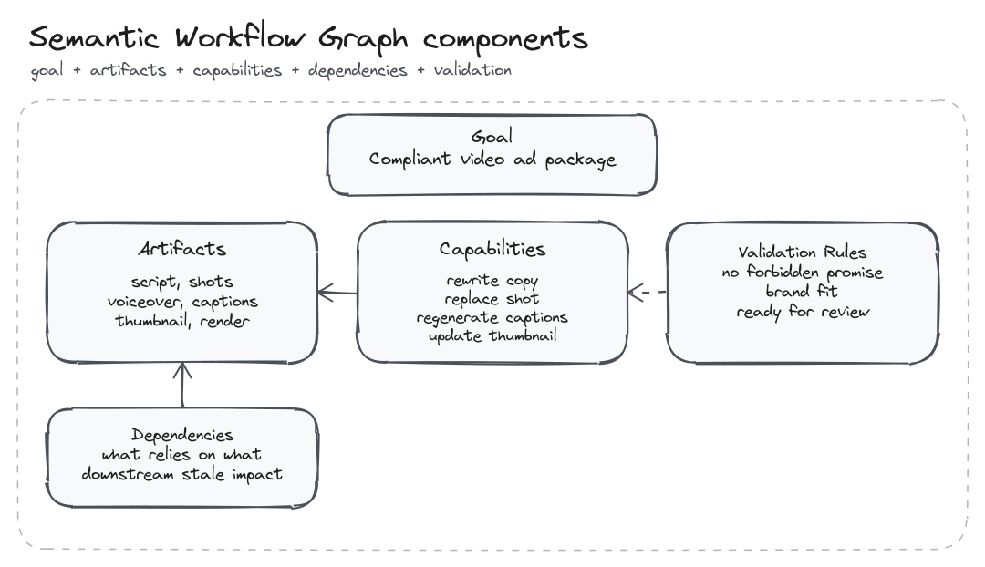
This gives the agent a better guide than a simple route map.
With this broad view of the task the agent can handle a variety of situations by reasoning over the graph, instead of needing a bespoke procedure for every possible situation.
In the video ad example, the goal is not just “finish the next step.” The goal is to produce a compliant ad package. That process may require several steps, including revisions or variations. With the semantic information, the Agent can respond to improvised requests effectively, whereas it would struggle with only a Procedural Graph.
This fundamentally changes how we should think about a problem and the information needed to guide an agent.
Instead of asking, “What step comes next?”, ask:
What capability is needed? What input artifacts must exist? What output artifacts should be produced? What state does this node read and update? What downstream work depends on those outputs? What can run in parallel? What should happen if the output fails validation? What becomes stale if an earlier artifact changes?
Building a Semantic Workflow Graph
This guide shows how to set up the major pieces of a semantic workflow graph:
- the artifacts the system needs to create
- the specialized capabilities that can create or inspect those artifacts
- the dependency graph that decides what can run
- the shared state that records what has happened
- the validation gates that decide what is acceptable
- the derivative outputs that can reuse approved artifacts
- the recovery paths for broken or stale work
Start with artifacts
The easiest way to design a semantic graph is to begin with artifacts.
Ask what durable pieces of work the system needs to create. In the video ad production example, those artifacts might include the raw request, creative brief, audience profile, script, storyboard, shot list, asset plan, rendered cut, compliance report, and repair notes.
A single prompt can ask an LLM to “make the ad.” The work still has the shape of a sequence of artifacts.
The system needs to understand the request, extract constraints, define the audience, write the script, plan the scenes, gather or generate assets, render the cut, review it, and repair weak outputs.
A graph architecture models that work explicitly.
type Artifact =
  | "raw_input"
  | "creative_brief"
  | "audience_profile"
  | "script"
  | "storyboard"
  | "shot_list"
  | "asset_plan"
  | "rendered_cut"
  | "compliance_report"
  | "repair_notes";
Once the artifacts are visible, the graph can describe the capabilities that produce them.
This is where video production becomes a useful teaching example. Video work naturally has many specialized artifacts and steps: understand intent, inspect media, extract transcript, detect scenes, plan edits, generate intermediate assets, judge results, and repair weak outputs. The point is not that semantic workflow graphs are only for video. The point is that video makes the dependency structure easy to see.
Then define capability nodes
Each node declares what it needs and what it produces. That is the first move from a simple graph toward a semantic graph.
type BasicWorkflowNode = {
  id: string;
  needs: Artifact[];
  produces: Artifact[];
  run: string;
};
For a production system, the node can carry more meaning.
type SemanticWorkflowNode<TArtifact extends string = string> = {
  id: string;
  kind: "router" | "producer" | "validator" | "repair";
  capability: string;
  needs: TArtifact[];
  produces: TArtifact[];
  mayUpdateState: string[];
  run: string;
};
Now the workflow can be described as a set of semantic processors.
const nodes: SemanticWorkflowNode<Artifact>[] = [
  {
    id: "intake",
    kind: "producer",
    capability: "intent-analysis",
    needs: ["raw_input"],
    produces: ["creative_brief"],
    mayUpdateState: ["goal", "audience", "claims", "constraints"],
    run: "buildCreativeBrief"
  },
  {
    id: "audience",
    kind: "producer",
    capability: "audience-modeling",
    needs: ["creative_brief"],
    produces: ["audience_profile"],
    mayUpdateState: ["audience"],
    run: "defineAudience"
  },
  {
    id: "script",
    kind: "producer",
    capability: "ad-scriptwriting",
    needs: ["creative_brief", "audience_profile"],
    produces: ["script"],
    mayUpdateState: ["message", "claims", "cta"],
    run: "writeAdScript"
  },
  {
    id: "storyboard",
    kind: "producer",
    capability: "storyboard-planning",
    needs: ["script"],
    produces: ["storyboard", "shot_list"],
    mayUpdateState: ["scene_plan"],
    run: "buildStoryboard"
  },
  {
    id: "assets",
    kind: "producer",
    capability: "asset-planning",
    needs: ["storyboard", "shot_list"],
    produces: ["asset_plan"],
    mayUpdateState: ["asset_requirements"],
    run: "planAssets"
  },
  {
    id: "render",
    kind: "producer",
    capability: "video-rendering",
    needs: ["script", "storyboard", "asset_plan"],
    produces: ["rendered_cut"],
    mayUpdateState: ["render_path"],
    run: "renderAdCut"
  },
  {
    id: "compliance-review",
    kind: "validator",
    capability: "compliance-review",
    needs: ["creative_brief", "script", "rendered_cut"],
    produces: ["compliance_report"],
    mayUpdateState: ["quality_gate", "required_repairs"],
    run: "reviewRenderedAd"
  },
  {
    id: "repair",
    kind: "repair",
    capability: "video-repair",
    needs: ["compliance_report", "rendered_cut"],
    produces: ["repair_notes"],
    mayUpdateState: ["repair_plan"],
    run: "planVideoRepair"
  }
];
This is closer to the shape of a modern agent graph. The runtime can inspect the graph and understand that compliance-review is a validator, render is a producer, and intake updates the shared understanding of the user’s goal.
If you are familiar with DSPy, this should feel familiar. A DSPy Signature defines the local contract for an LLM step: these are the inputs, and these are the outputs. For example, a scriptwriting step might take a creative brief and compliance constraints, then return an ad script. DSPy frames signatures as a way to define the input and output behavior of a language-model program. Source: https://dspy.ai/getting-started/first-program/
class BuildAdScript(dspy.Signature):
    """Create a video ad script from a creative brief."""

    creative_brief = dspy.InputField()
    compliance_constraints = dspy.InputField()
    script = dspy.OutputField()
A workflow graph applies the same instinct at the system level. The signature tells one module what shape its task has. The graph tells the whole workflow how modules depend on each other.
{
  id: "script",
  needs: ["creative_brief", "audience_profile"],
  produces: ["script"],
  run: "BuildAdScript"
}
So the relationship is simple: DSPy Signatures solve the local contract problem. A graph solves the global coordination problem.
The signature says what one step needs and returns. The graph says when that step is allowed to run, which artifacts it unlocks, and what downstream work becomes stale if its inputs change.
This is the shift: the system is no longer managing a vague prompt chain. It is managing typed artifact production.
Add dependencies
After artifacts and capabilities, add dependency rules.
A dependency is the reason one node has to wait for another. In the video ad workflow, the render node should not run just because the user asked for a video. It needs the script, storyboard, and asset_plan first.
Do not treat that as a loose note beside the graph. Make it part of the graph declaration.
type DependencyGraph<TArtifact extends string = string> = {
  nodes: SemanticWorkflowNode<TArtifact>[];
};

const dependencyGraph: DependencyGraph<Artifact> = {
  nodes: [
    {
      id: "script",
      kind: "producer",
      capability: "ad-scriptwriting",
      needs: ["creative_brief", "audience_profile"],
      produces: ["script"],
      mayUpdateState: ["message", "claims", "cta"],
      run: "writeAdScript"
    },
    {
      id: "storyboard",
      kind: "producer",
      capability: "storyboard-planning",
      needs: ["script"],
      produces: ["storyboard", "shot_list"],
      mayUpdateState: ["scene_plan"],
      run: "buildStoryboard"
    },
    {
      id: "assets",
      kind: "producer",
      capability: "asset-planning",
      needs: ["storyboard", "shot_list"],
      produces: ["asset_plan"],
      mayUpdateState: ["asset_requirements"],
      run: "planAssets"
    },
    {
      id: "render",
      kind: "producer",
      capability: "video-rendering",
      needs: ["script", "storyboard", "asset_plan"],
      produces: ["rendered_cut"],
      mayUpdateState: ["render_path"],
      run: "renderAdCut"
    }
  ]
};
Now the dependency rule is not floating around as prose. It is encoded in needs.
Read the render node literally:
scriptmust exist.storyboardmust exist.asset_planmust exist.- only then can
renderAdCutproducerendered_cut.
The graph does not need a separate dependency language yet because needs and produces already form one. Each node says which artifacts it consumes and which artifacts it creates.
If the user asks for rendered_cut, the runtime can walk backward through the graph:
rendered_cutis produced byrender.renderneedsscript,storyboard, andasset_plan.asset_planis produced byassets.assetsneedsstoryboardandshot_list.storyboardandshot_listare produced bystoryboard.storyboardneedsscript.
That is the conceptual layer. The graph explains what must exist before a capability can run.
A scheduler might later implement that check with small helper functions:
function canRun(node: SemanticWorkflowNode<Artifact>, artifacts: Set<Artifact>) {
  return node.needs.every(input => artifacts.has(input));
}
If all required inputs exist, the node can run. If one is missing, the node waits.
The next question is just as important: what exactly is missing?
function missingInputs(node: SemanticWorkflowNode<Artifact>, artifacts: Set<Artifact>) {
  return node.needs.filter(input => !artifacts.has(input));
}
Those helpers are not the graph. They are one possible way a CLI, worker, or orchestrator could inspect the graph. The important design choice is to keep dependency truth in the node contracts, then let runtime code ask questions of those contracts.
Add validation gates
Dependencies say whether a node has enough inputs to run. Gates say whether an output is good enough to unlock the next part of the workflow.
In the video ad example, rendering a cut is not the same as approving a cut. A rendered ad may still make an unsupported claim, violate brand rules, use the wrong call to action, or fail a platform requirement.
That is why compliance-review is a validator node.
The node is the work that runs. The gate is the decision produced by that work.
type Gate = {
  name: string;
  passed: boolean;
  blockingIssues: string[];
};

type ComplianceReport = {
  artifact: "compliance_report";
  gate: Gate;
  notes: string[];
};
Now the validator node has a clear job: inspect the rendered cut and produce a compliance_report that contains the gate result.
{
  id: "compliance-review",
  kind: "validator",
  needs: ["creative_brief", "script", "rendered_cut"],
  produces: ["compliance_report"],
  mayUpdateState: ["quality_gate", "required_repairs"],
  run: "reviewRenderedAd"
}
So the relationship is:
renderproducesrendered_cut.compliance-reviewconsumesrendered_cut.compliance-reviewproducescompliance_report.compliance_report.gate.passeddecides whether delivery or derivative work can proceed.
The important part is not the exact type. The important part is the control rule: downstream delivery should wait until the required gate passes.
This is different from a normal dependency. A dependency asks, “Does the input exist?” A gate asks, “Is the input acceptable?”
Add derivatives
Real production workflows rarely stop at one final artifact.
Once the system has a script, storyboard, asset plan, and rendered cut, it can create derivative outputs: a six-second cut, a vertical cut, captions, a thumbnail, a platform-specific version, or alternate calls to action.
Those derivatives should also be represented as artifacts.
type DerivativeArtifact =
  | "six_second_cut"
  | "vertical_cut"
  | "caption_file"
  | "thumbnail"
  | "platform_variant";
The graph can then describe which derivatives can run from the current source material.
{
  id: "vertical-variant",
  kind: "producer",
  capability: "video-reformatting",
  needs: ["rendered_cut", "compliance_report"],
  produces: ["vertical_cut"],
  mayUpdateState: ["channel_plan"],
  run: "createVerticalVariant"
}
This is where graphs become more useful than linear pipelines. A linear pipeline tends to assume one path to one output. A graph can reuse the same approved source artifacts to produce several downstream outputs.
Add repair and staleness
The last piece is change.
If the script changes, the storyboard may no longer match. If the storyboard changes, the asset plan may no longer match. If the rendered cut changes, the compliance report may no longer be trustworthy.
That means useful artifacts should know what produced them.
type StoredArtifact = {
  type: Artifact;
  value: unknown;
  producedBy: string;
  inputHashes: Record<string, string>;
  createdAt: string;
};
With input hashes, the runtime can tell whether an artifact was produced from the current inputs or from older inputs.
function isStale(
  artifact: StoredArtifact,
  currentInputHashes: Record<string, string>
) {
  return Object.entries(artifact.inputHashes).some(
    ([key, oldHash]) => currentInputHashes[key] !== oldHash
  );
}
If the script changes, anything downstream that was produced from the old script can be marked stale.
This is also how the system repairs failed work without starting over.
If the script is good but the storyboard is weak, rerun the storyboard node. If the storyboard changes, rerun only the asset plan and render nodes. If the rendered cut fails compliance review, rerun the repair branch while preserving the creative brief, audience profile, approved script, and so forth.
That is the practical meaning of semantic graph design. The graph is an execution plan, a dependency map, a validation system, and a recovery structure for the work.
How the agent uses the graph
A real implementation of the tutorial above can be a small graph package:
artifact-schemas.jsoncapability-registry.jsonworkflow.graph.jsonvalidation-gates.jsonrepair-policy.json
Those files map directly to the sections above: artifact types, capability nodes, dependency planning, validation gates, and stale-artifact repair.
They are files the service knows about, not files the agent has to discover on its own. In a web app, the backend loads the graph package for the selected workflow. Then it gives the agent the relevant part of that package in its system instructions or tool context: the target artifact, the artifacts that already exist, the missing inputs, and the capability it is allowed to run next.
During a run, the service creates run state and output artifacts separately:
run-state.jsonartifacts/script.jsonartifacts/storyboard.jsonartifacts/asset-plan.jsonartifacts/rendered-cut.jsonartifacts/compliance-report.json
From there, the agent can use the graph to infer the execution process: what to create first, what can be edited safely, what needs to change after feedback, and which downstream artifacts need to be checked or regenerated.
The graph does not replace the agent’s judgment. It gives that judgment a structured way to move through the work, make corrections, and keep the run coherent.
I hope this gives you a useful starting point. You probably will not hand-code every graph file yourself, but you now have the concepts, terminology, and pattern needed to ask a coding agent to implement one, review what it builds, and discuss the architecture clearly.